Sequence of a typical assembly production
The production or the Electronics Manufacturing Service (EMS) of a printed circuit board to be assembled can be divided into the following work steps:
- Production of the printed circuit board (PCB)
- Deposition of solder paste on the future contact points of the components. The highly viscous solder paste consists of tiny tin balls and flux.
- Assembly of the printed circuit board. SMD components (SMD, Surface Mounted Devices) are now placed in the solder paste depots. They initially adhere there only through the adhesive effect of the solder paste. The assembly process is automated.
- Soldering the SMD components. The solder paste melts under the influence of heat and firmly bonds the SMD components to the circuit board.
- Assembly of the printed circuit board with conventional, wired components using THT technology (THT, Through Hole Technology). This is done by inserting the connection wires into the holes made for this purpose in the circuit board.
- Soldering of the THT components. The soldering is preferably done with a robot, but can also be done manually.
- Inspection of the assembly result, visually and electrically by specific measurement technology. For complex assemblies or series products, precisely designed test systems are designed.
Application of solder paste
Paste printing can be done in different ways. Mostly screen printing or stencil printing is used. Both processes have in common that where an opening has been cut in a stainless steel mesh or sheet with a high-precision laser, the solder paste can wet the PCB. Each circuit board layout therefore requires a specially manufactured screen or stencil. The pastes used are precisely matched to the mesh count of the screen or to the stainless steel stencil. The quality of the print is checked by visual inspection.
Assembly of the printed circuit board
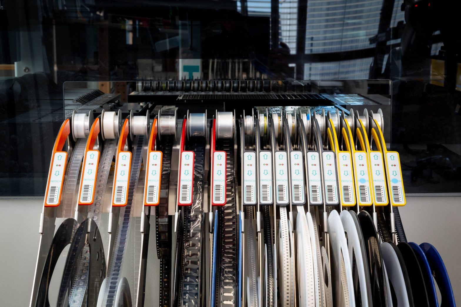
The components are set up on rolls, belts, trays or in bars on the pick-and-place machine. The components are removed from the respective packaging by the head of the machine by means of a vacuum, centered and aligned in the machine and then assembled to the correct X/Y coordinate of the printed circuit board. This placement process is called “pick-and-place”.
Soldering of the components
For automatic soldering of the assemblies, we prefer to use vapor phase soldering, which is particularly gentle on components. Here, the heating of the printed circuit board is achieved by the condensation heat of a steam (Galden, LS230). The maximum temperature that the assembly can reach with this soldering process is limited to 230°C. The energy requirement for the assembly is automatically controlled by the soldering time. During soldering, the solder paste melts, makes the electrical connection and the flux evaporates. After the assembly has cooled and dried, the SMD components are permanently and electrically connected to the PCB.
THT components are soldered manually using a soldering iron or automatically using a soldering robot. This robot reproduces the manual soldering process by machine and thus achieves very reproducible results. Manual work is limited to handling the assembly and threading THT components.
Checking the placement/assembly result
Soldering is not the end of the assembly process. In order to confirm the quality produced or to detect defects at an early stage, an AOI (Automatic Optical Inspection) check can be carried out. Here, an AOI system uses several camera systems to automatically inspect the printed circuit board and compares the result with a reference that has been rated as good. If there are any deviations, the operator is informed about the exact defect pattern, who then corrects the defect or rejects the PCB.
Much more important, however, is the electrical test of the manufactured assembly. For this purpose, the assembly is connected to specific test equipment and usually tested automatically.